
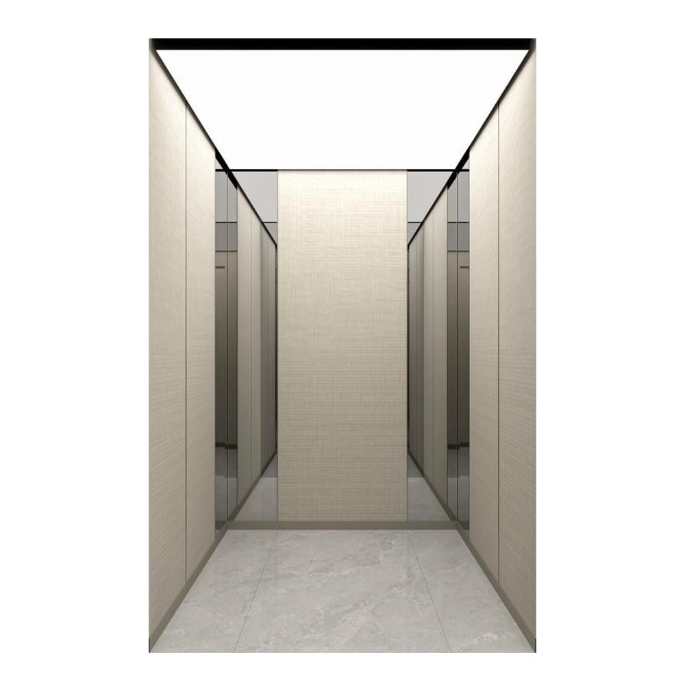
Passenger elevator
The zLift:
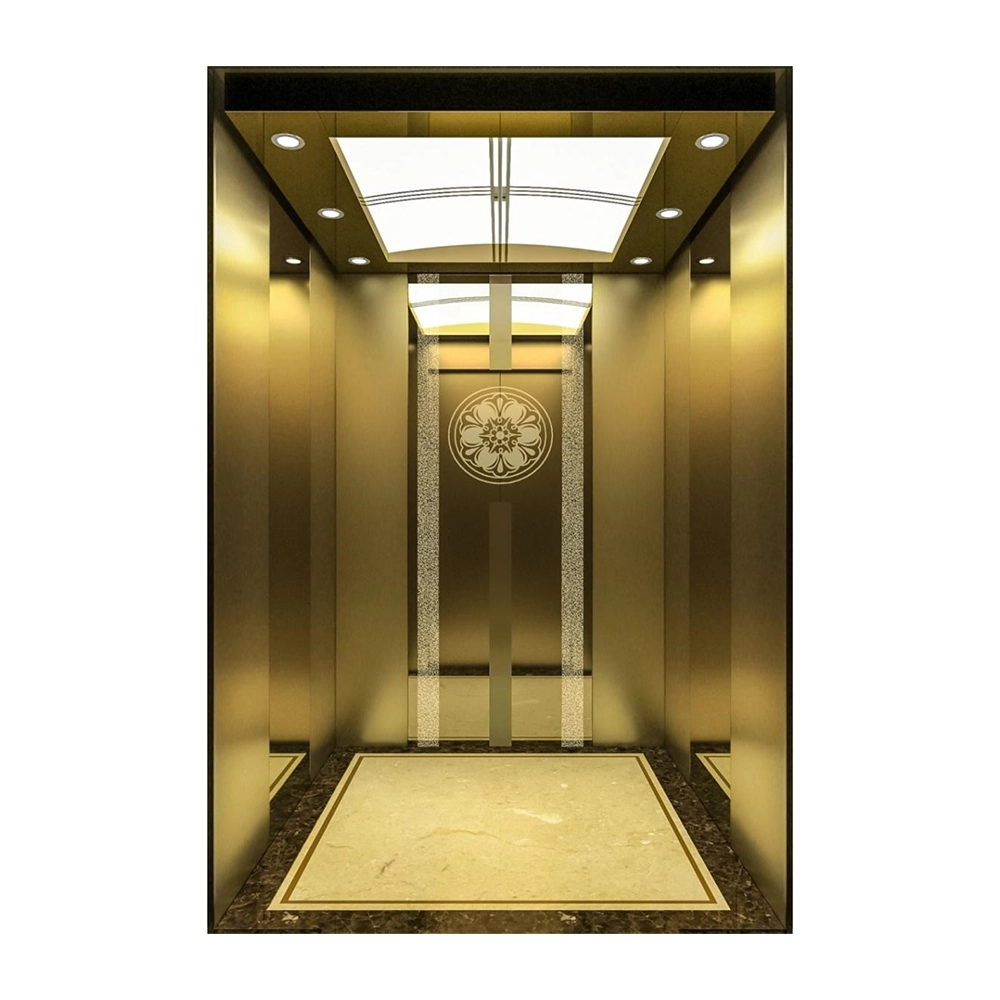
The zLift is a 2:1 suspended, centrally guided machine roomless passenger elevator with a frequency-controlled, gearless drive and was specially developed for multi-storey residential and office buildings. It can be equipped with three different drive sizes and, as of a load capacity of 1,600 kg, also is suitable as a bed elevator for nursing homes and hospitals. It combines a high level of ride comfort with state-of-the-art, energyefficient drive technology.
The zLift is available in practically all freely-selectable car layouts starting from 900 mm in car depth, 225 kg to 2,000 kg in load capacity and in speeds of 1.0 m/s and 1.6 m/s. Depending on the load capacity, speed and optional cabin equipment, shaft pits optionally can be reduced to 400 mm and shaft heads minimized to 2,400 mm.
The zLift is equipped with coated steel ropes. Its maximum conveying height is 45 m.
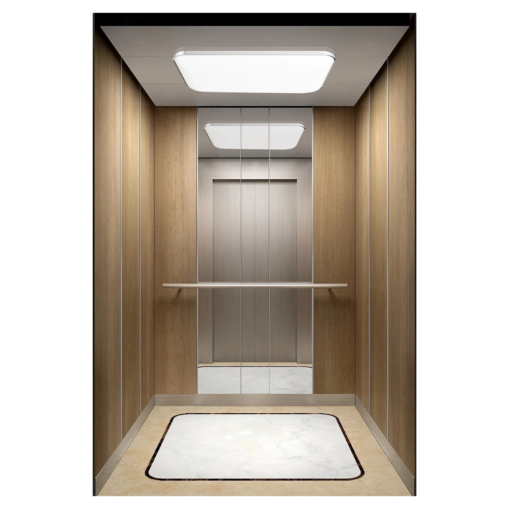
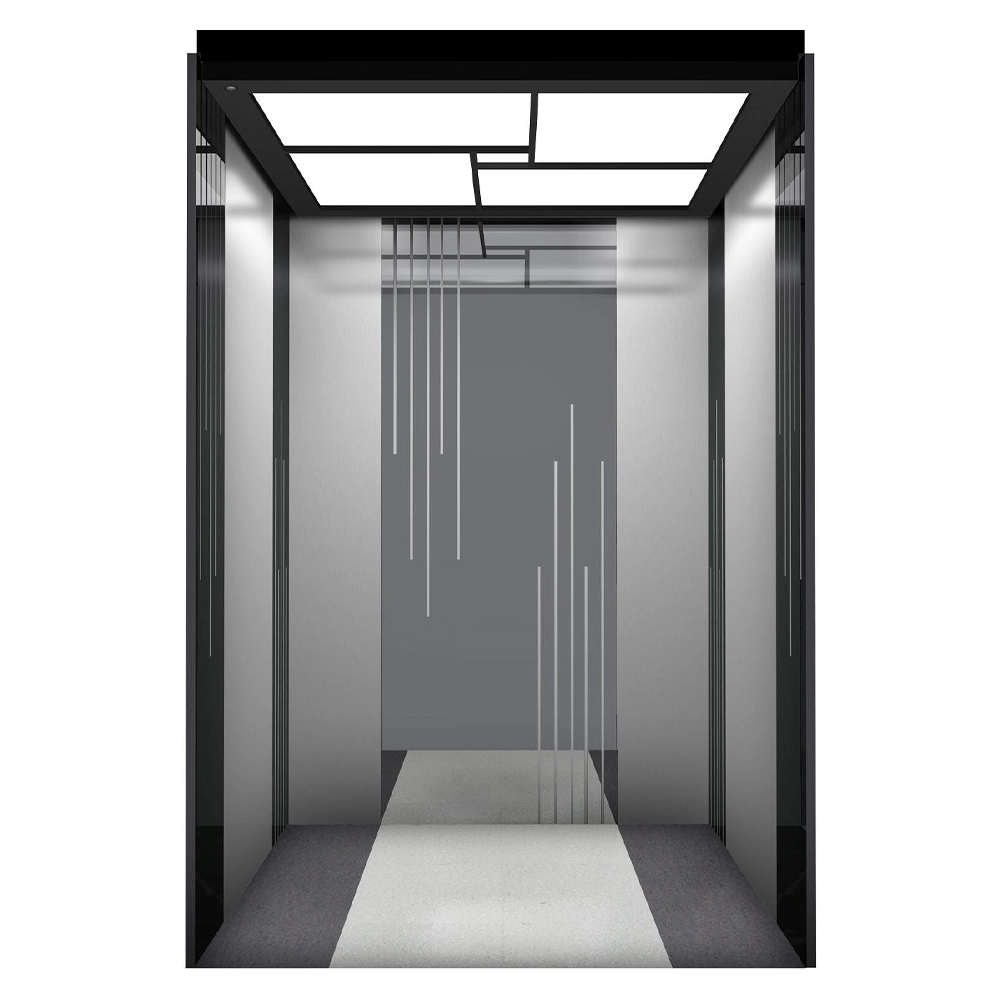
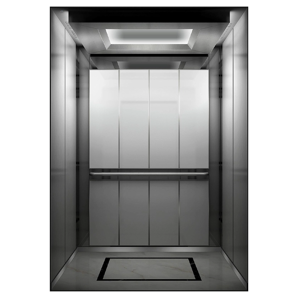
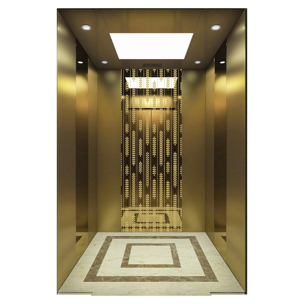
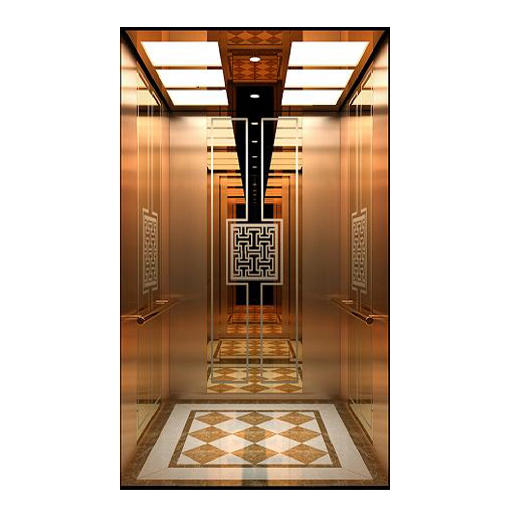
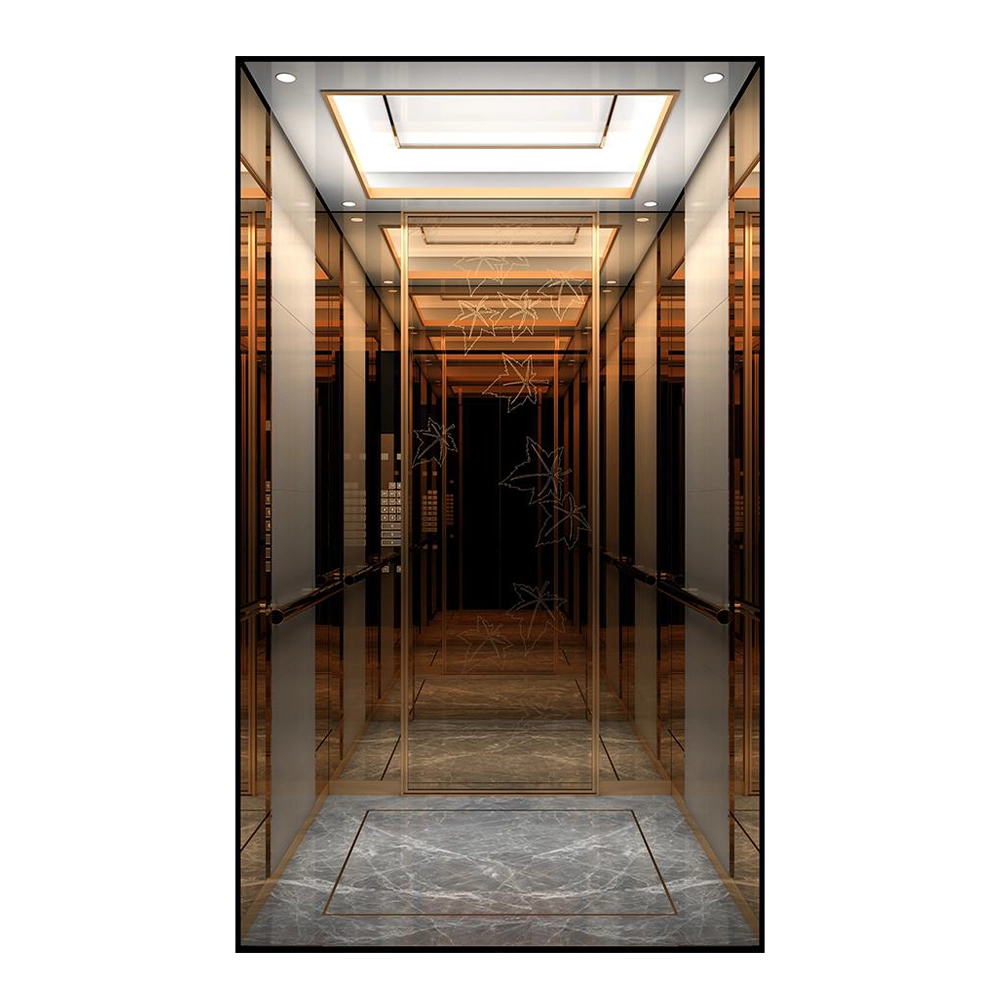
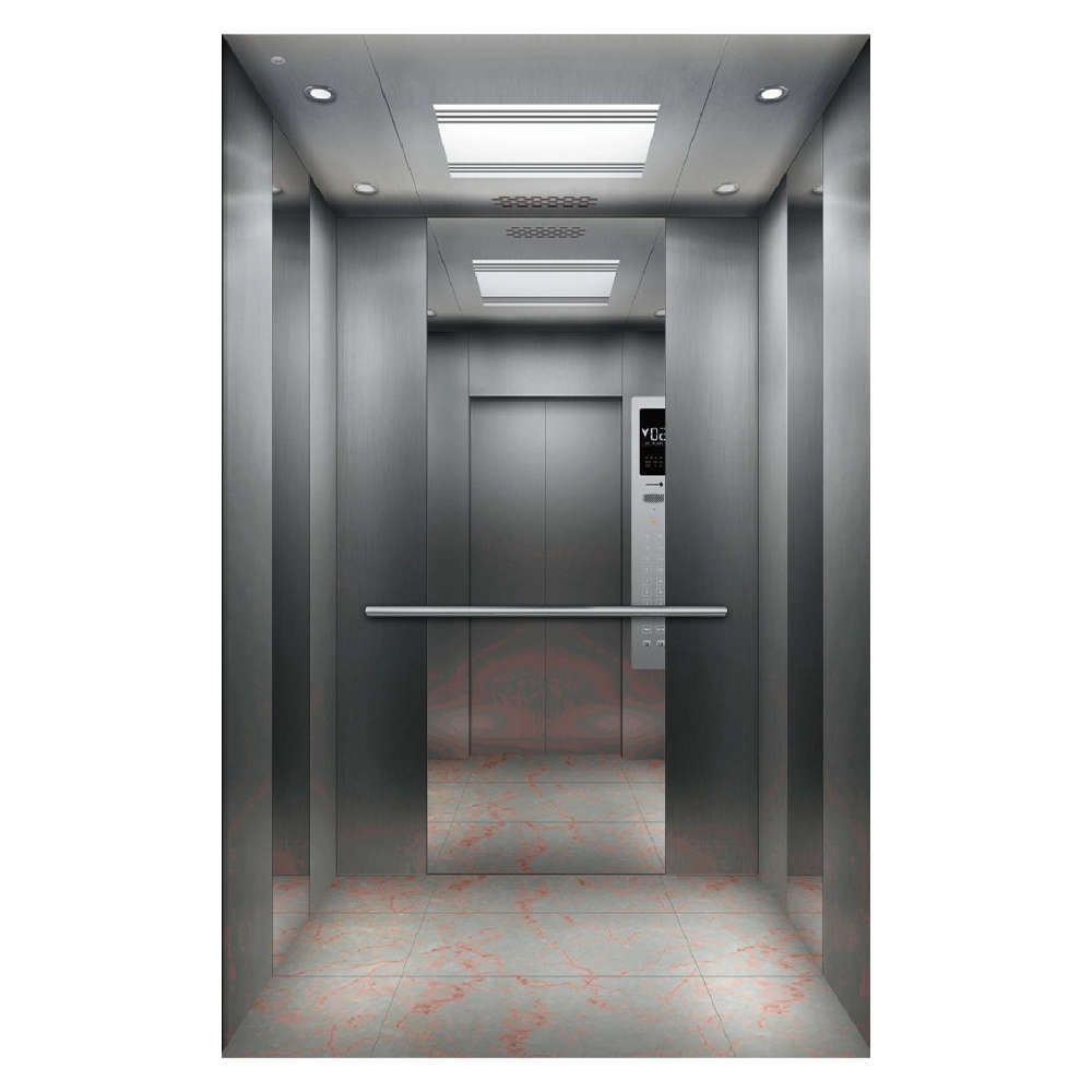
In principle, all cabin equipment options listed on the following pages and the individual iLift DESIGN program also are available for the zLift.
zLift – Technical features
| Standard | |
| Duty Load | from 225 kg to 2,000 kg with variable cabin layouts |
| Travel Height | up to 45 m travel from 2 to 19 stops |
| Speed | 1.0 m/s and 1.6 m/s |
| Door types | central and one-sided opening |
| Shaft pits | from 400 mm (optional) depending on load capacity, speed and cabin design |
| Shaft heads | from 2,500 mm (optional) depending on load capacity, speed and cabin design |
| Motor drive | gearless, frequency controlled (in shaft head) |
| Control | plug-and-play, state of the art MPK4i control system technology mounted in a separate control cabinet (2,000 mm h x 400 mm w x 230 mm) in the uppermost landing material finish primed or in brushed stainless steel |
| Functions |
|
| Regulations | EN 81-20, EN 81-50, EN 81-58, ARL 2014/33/EG |
| Options | |
| Functions |
|
| Regulations | EN 81-70, EN 81-71, EN 81-73, GOSTP53780-2010 |
Variant specifications
| zLift | ||||||
| Duty load (Q) | Kg | 225 ≤ Q ≤ 450 | 450 < Q ≤ 630 | 630 < Q ≤ 1,000 | 1,000 < Q ≤ 2,000 | |
| Suspension | 2:1 | |||||
| Speed | m/s | 1.0 – 1.6 | ||||
| Travel Height max. | m | 45 | ||||
| Rope diameter | mm | 6.5 (coated) | ||||
| Cabin | ||||||
| Cabin witdh (CW) | mm | 700 – 1,400 | 900 – 1,660 | 900 – 2,180 | 1,000 – 2,620 | |
| Cabin depth (CD) | mm | 900 – 1,850 | 900 – 1,850 | 1,000 – 2,660 | 1,500 – 3,000 | |
| Cabin Height (CH) | mm | 2,000 – 2,500 | ||||
| Doors | ||||||
| Door width | mm | 700 – 2,400 | ||||
| Door height | mm | 2,000 – 2,400 | ||||
| Door type |
|
|||||
| Through-cabin | optional | |||||
| Shaft | ||||||
| Shaft width | mm | CW + 500 | CW + 500 | CW + 500 | CW + 640 | |
| Shaft depth T2 / C4 Door type | mm | CD + 325 | CD + 325 | CD + 325 | CD + 325 | |
| Shaft depth with through-cabin T2 / C4 Door type | mm | CD + 530 | CD + 530 | CD + 530 | CD + 530 | |
| Shaft depth C2 Door type | mm | CD + 255 | CD + 255 | CD + 255 | CD + 255 | |
| Shaft depth with through-cabin C2 Door type | mm | CD + 390 | CD + 360 | CD + 390 | CD + 390 | |
| Shaft pit (Standard) | mm | ≥ 400 (1,050) | ||||
| Shaft head (Standard) | mm | ≥ 2,500 (CH + 1,200) | ||||
Note: The cabin height refers to the raw ceiling. Suspended ceilings reduce the clearance height within the cabin accordingly.
T = Telescopic doors (left or right opening), C = Centrally opening doors, 2/3/4/6 = Number of door panels
Certain combinations are not possible.