
Passenger elevator
The xLift
The xLift is available in almost all freely-selectable car layouts from 3,000 mm in car depth, 3,000 kg to 6,500 kg in load capacity and at speeds of between 0.5 m/s to 1.6 m/s. Depending on the load capacity, speed and optional cabin equipment, shaft pits optionally can be reduced to 1,200 mm and shaft heads minimized to 3,800 mm.
The xLift is equipped with steel cables. The maximum conveying height is 45 m.
Strong, stronger, xLift!
The xLift is equipped with steel cables. The maximum conveying height is 45 m
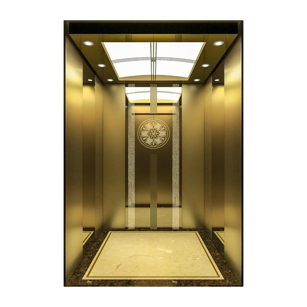
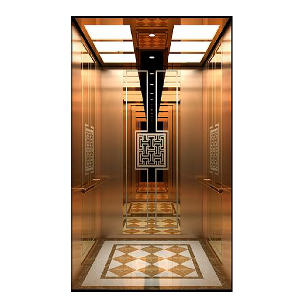
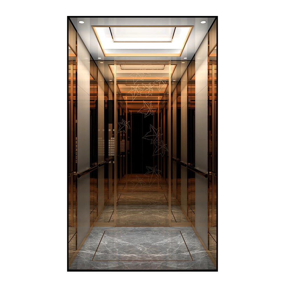
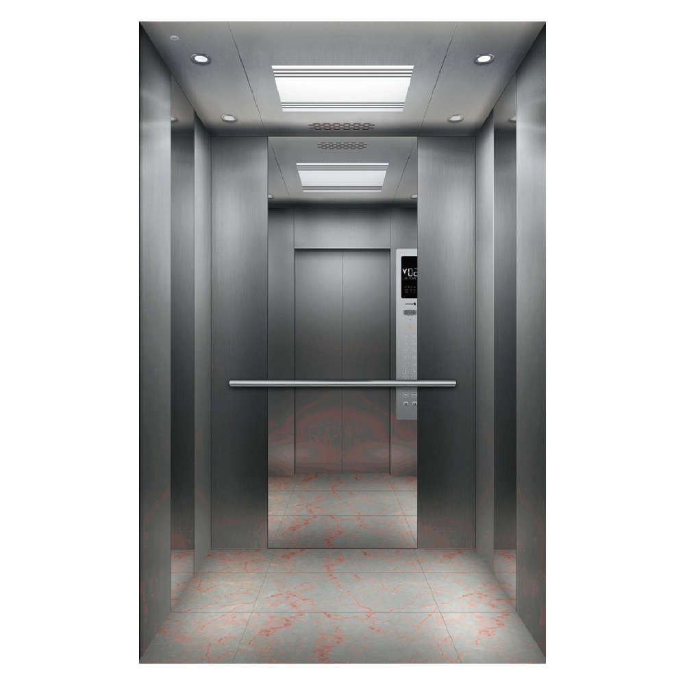
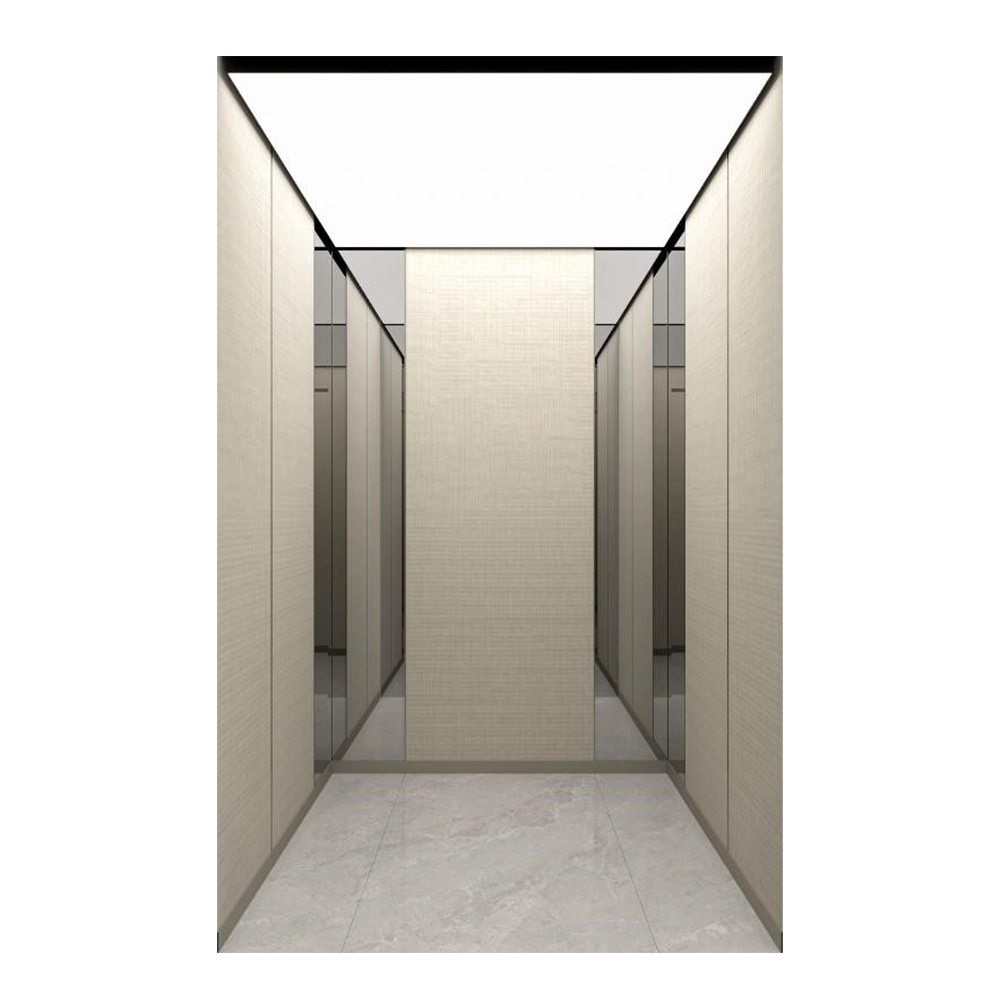
All cabin equipment options listed on the following pages as well as the individual iLift-DESIGN program also are available for the xLift.
Technical Data Overview
| Standard | |
|---|---|
| Duty Load | from 630 kg to 3,000 kg with variable cabin layouts |
| Travel Height | up to 80 m travel from 2 to 26 stops |
| Speed | 1.0 m/s to 2.5 m/s |
| Door types | center or side opening |
| Shaft pits | from 550 mm (optional) depending on load capacity, speed and cabin design |
| shaft heads | from 2,500 mm (optional) depending on load capacity, speed and cabin equipment |
| Drive | gearless, frequency-controlled (in the shaft head) |
| control | Plug-and-play processor with MPK4i technology in the top station in a separate control cabinet (400 × 230 × 2,000 mm) Material design primed or in brushed stainless steel |
| Functions | • Intercom connection between car and control cabinet • Emergency evacuation with display of speed, direction of rotation, and door zone area |
| Regulations | EN 81-20, EN 81-50, EN 81-58, ARL 2014/33/EG |
| Options | |
|---|---|
| Functions | • Through-loading • Doorman intercom • Automatic evacuation function to the next stop • With door opening via separate UPS • Control cabinet can be positioned up to 15 m away from the base position at the top stop • Frame control can be positioned vertically up to 15 m away from the top stop • Group control for up to four systems • Group control for up to four systems • Lift monitoring • Cabin fan optionally with button in the control panel or automatic during travel with coasting |
| Regulations | EN 81-70, EN 81-71, EN 81-73, GOSTP53780-2010 |
Product Specifications
| sLift | |||||
|---|---|---|---|---|---|
| load capacity (Q) | Kg | 630 < Q ≤ 1,250 | 1.250 < Q ≤ 1,600 | 1,600 < Q ≤ 2,000 | 2,000 < Q ≤ 3,000 |
| Suspension | 2:1 | ||||
| Speed | m/s | 1.0 bis 2.5 | |||
| Travel height max. | m | 80 | |||
| Rope diameter | mm | 6.5 (steel rope) | 8 / 10 (steel rope) | ||
| Car | |||
|---|---|---|---|
| Cabin witdh (CW) | mm | 700 – 2,300 | 1,400 – 2,900 |
| Cabin depth (CD) | mm | 1,400 – 2,600 | 2,000 – 2,400 |
| Cabin height (CH) | mm | 2,000 – 2,500 | 2,000 – 2,800 |
| Doors | |||
|---|---|---|---|
| Door width | mm | 700 – 2,500 | |
| Door heights | mm | 2,000 – 2,400 | |
| Door Types | T2 / T3 / C2 / C4 | T2 / T3 / C2 / C4 / C6 | |
| Through-loading | optional | ||
| Shaft | |||||
|---|---|---|---|---|---|
| shaft widths | mm | KB + 550 | KB + 640 | KB + 720 | KB + 880 |
| Shaft depths door type T2 and C4 | mm | CD + 325 | |||
| Shaft depths door type T2 and C4 with through-loading | mm | CD + 530 | |||
| Shaft depth T3 / C6 Door type | mm | KT + 415 | |||
| Shaft depth with through-cabin T3 / C6 Door type | mm | KT + 710 | |||
| Shaft depths door type C2 | mm | CD + 255 | |||
| Shaft depth with through-cabin C2 Door type |
mm | KT + 390 | |||
| Shaft pit (Standard) | mm | ≥ 550 (1,050) | ≥ 750 (1,050) | ≥ 950 (1,050) | |
| Shaft head (Standard) | mm | ≥ 2,500 (KH + 1,200) | ≥ 2,750 (KH + 1,450) | ||
The respective cabin height describes the measurement to the base ceiling. Suspended ceilings must be deducted from this and reduce the clear dimension accordingly.
T = Telescopic door (opening left or right), C = Centrally opening door, 2/3/4/6 = Number of leaves
Some combinations are not possible.